Back to top

The Role of FEA-Based Verification Software in Offshore, Marine, and Industrial Structural Engineering

Running the finite element model of a platform jacket takes hours. Getting the results into a form a classification society…

The Role of FEA-Based Verification Software in Offshore, Marine, and Industrial Structural Engineering

28th August 2026

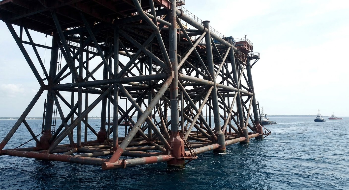
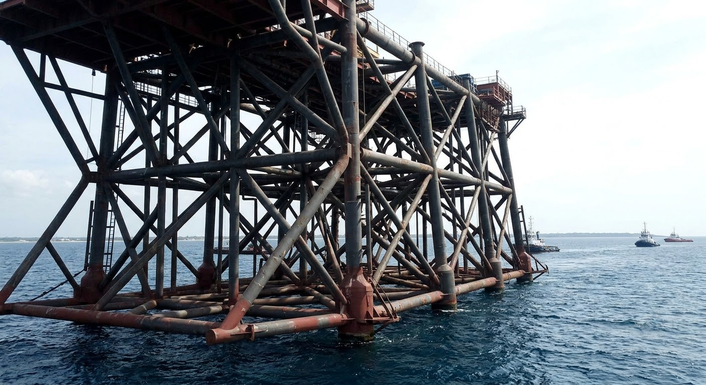
Running the finite element model of a platform jacket takes hours. Getting the results into a form a classification society will accept takes weeks.

The gap has nothing to do with solver speed. It opens at the code verification stage: between the array of stresses and displacements FEA produces and the statement that a structure satisfies DNV-OS-C101 and API RP 2A sit thousands of individual checks against standard formulas.

This article breaks down why that stage stopped scaling by hand in offshore, shipbuilding, and industrial equipment, and which part of it FEA-based verification software covers.

Load Case Combinatorics

A typical fixed platform assessment is built around two categories of design condition: normal operation with a one-year return wave and extreme storm with a hundred-year one. Each breaks down by wave approach direction; each direction needs its own wave, wind, and current definition, and the crest position steps along the structure in increments of a few degrees.

Then the checking starts. A unity check for combined stress, axial force, bending about both axes, and shear runs on every member under every design condition.

One detail carries most of the risk: the governing condition varies from member to member. One brace peaks under a wave from 0°, its neighbor at 45°. An engineer who checks only the obviously critical members under the obviously worst combination will likely miss the actual governing combination.

What Happens When Load Coverage Falls Short

In June 2013, the container ship MOL Comfort broke in two in the Indian Ocean. Both hull sections later sank.

The industry response is on record in an IACS press release: an expert group formed in early 2014 developed Unified Requirement UR S34, in force since 1 July 2016. The document sets a minimum set of load cases for finite element strength assessment of container ships and requires global hull analysis for vessels from 290 meters and cargo hold analysis for vessels from 150 meters.

IACS words it carefully. UR S34 does not establish an overall FE analysis standard; it sets functional requirements so that analyses are undertaken with suitable load cases considered.

Classification societies treat incomplete load case coverage as a demonstrated risk.

Three Industries, Three Sets of Codes

Offshore work runs on DNV-OS-C101, renamed in July 2023 to Structural Design of Offshore Units and merging the LRFD and WSD methods. Alongside it sit DNV-RP-C203 for fatigue, API RP 2A and ISO 19902 for fixed steel structures. The Norwegian shelf adds NORSOK N-004, with detailed accidental limit state provisions covering blast, fire, collision, and dropped objects.

In shipbuilding, hull strength assessment splits into tiers: a global model of the vessel, a three-cargo-hold model for the midbody, and local fine-mesh models for openings, brackets, and web frame connections. Meshing rules differ between tiers, and so do the permissible utilisation factors.

Industrial structures stay in Eurocode 3 and AISC 360 territory, with separate codes for cranes and lifting equipment. A change is underway here as well: the second generation of Eurocodes must be published by national standards bodies no later than 30 September 2027.

Few real projects stay inside one code family. An FPSO topside pulls global strength from DNV, accidental loads from NORSOK, and topside steel connections from Eurocode 3 and other standards.

Spectral Fatigue and Panel Buckling

ABS describes spectral-based fatigue analysis as a complex and numerically intensive technique. A structural analysis runs at each frequency, each wave heading, and each loading condition to build the stress transfer function. Heading increments must not exceed 30°, which puts at least twelve headings around the full circle. Cumulative damage then sums across every cell of the wave scatter diagram through the Palmgren-Miner rule. And that is per hot spot location.

A topside deck or a ship hull holds hundreds to thousands of stiffened panels, and under DNV-RP-C201 the panels and their constituent plates and stiffeners are assessed through different buckling formulations, with checks depending on the structural configuration and governing stress state.

Fatigue and buckling checks fit into a single cycle when the code formulas live inside the post-processing environment. Structural design and analysis software such as SDC Verifier recognises panels, welds, beam members, and joints in the model automatically, applies the selected code to every recognised element under every combination, and identifies the governing combination by peak utilisation factor separately for each check. Post-processing that takes days by hand comes down to minutes.

Two Quantities That Get Misread Most Often

Buckling length. Here Le = K × L, where K depends on end restraint conditions, not on the physical length of the member. A pinned-pinned column gives K = 1.0. The same column inside a rigid moment frame gives a different value, driven by the relative stiffness of the connecting members. Strictly, K for a column in a frame follows only from a stability analysis of the whole frame, and nomographs such as the AISC alignment charts remain simplifications of that problem.

Hot spot stress. The peak nodal stress from FEA is not the quantity to use here: it is mesh dependent and climbs without converging at a singularity with every refinement. The correct value comes from linear extrapolation of read-out points set back from the weld toe. ABS specifies a 1:1 element aspect ratio immediately at the hot spot and quadrilateral shell element corner angles within 45 to 135 degrees. The stress concentration factor does not always exceed unity: values below 1.0 are valid in some situations.

Both quantities need context that a single-member results table does not carry.

The Report as the Object of Review

Calculation documentation for class is not a final number. The Indian Register of Shipping guidelines on finite element methods IRS-G-DES-05, Revision 01 of December 2024, list thirteen mandatory submission items:

  • Drawings and sketches of the structure
  • Detailed description of structural modeling, including all assumptions and any deviations from plans
  • Plate thickness and beam section plots for decks, profiles, and transverse sections
  • Boundary conditions
  • All loading conditions reviewed, with calculated hull girder shear force, bending moment, and torsional moment distributions
  • Applied loads with confirmation that individual and total loads are correct
  • Plots and results of the structural analyses carried out
  • Summary and plots of deflections
  • Stress plots, von Mises and in-plane components, for decks, profiles, and transverse sections
  • Plate and stiffened panel utilisation ratios in buckling and ultimate strength failure modes
  • Tabulated results showing compliance with the design criteria
  • Proposed scantling amendments, with revised assessment of stresses, yield, buckling, and fatigue

The last item on the list is the computer program used in the analysis, including its version and date.

Editions bring their own difficulty. DNV publishes its main rule edition annually in July, entering into force the following January. The difference between editions is not always cosmetic: the DNV-RP-C203 update in 2024 changed calculated fatigue endurance for a typical monopile weld detail by roughly a factor of three. A report that does not state the governing edition loses its evidentiary weight when the structure gets reassessed.

When the model changes, all thirteen items have to line up again. Manually rebuilding that package after every geometry iteration is the operational load.

What This Means for Schedule

Reports with stress categorisation errors or an incomplete set of loading conditions typically go through two or three revision cycles, adding weeks to the schedule. A single error is not isolated either. Full structural verification is built from hundreds of repetitive checks, and one misapplied formula is enough to send the package back for review.

Automation delivers a second effect beyond compliance. With code checks inside the calculation cycle, it becomes possible to find the minimum plate thickness or profile section that keeps the utilisation factor under the allowable. Weight reduction without stepping outside the standard.

FEA computes stresses. A classification society accepts a document in which those stresses are matched against the formulas of a specific edition of a specific standard for every element under every loading condition. Verification software closes the distance between the two.

Categories: Tech

Our awards

Discover Our Awards.

See Awards

You Might Also Like